Sound System Input Stages
Sound System Project
Disclaimer: This project involves high-power electronics, including circuits that can carry dangerous voltages and currents. Improper design, construction, or handling may result in electric shock, burns, fire, equipment damage, or personal injury. The information shared here is for educational and documentation purposes and is not a complete guide. Therefore it should not be followed blindly. Stay safe.
In the past couple of days during my spare time I have been working on the input stages of the sound system. this is everything leading to the amplifier, more specifically: headphone jack input, volume control, eq and buffering.
Changes From Original Plan
I ended up changing the process order, as research led to me finding that it is more common to buffer the input, following this with volume control and finally the eq stage. The buffer early on would prevent loading effects on the input device by providing high impedance.
Another major difference I made was switching to a dual power supply. My original plan was to use dc coupling to push signals to entirely positive voltage range and operate rail to rail op amps with single supply. However I noticed that dual power supplies cost relatively the same as single supply and therefore I though it would save the hassle of having to add dc offsets and decided to just go with the dual power supply.
Input Stage
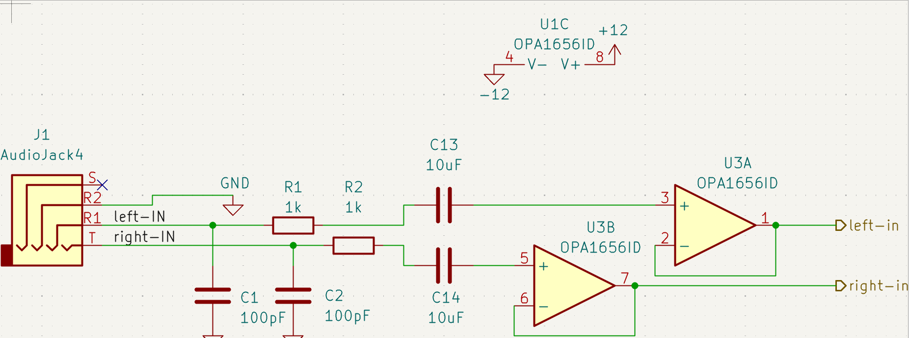
The first step in the audio processing is the headphone jack. this acts as the entrance point for audio signals into the system. I found that modern devices use a standard called CTIA for TRRS jacks. TRRS are the headphone jacks that include ground, 2 stereo lines and a microphone line. They are compatible with TRS as well (no microphone line).
After the signal enters the headphone jack I use a filter to remove any unwanted noise. I made sure that the cut-off frequency of the filter wouldn’t remove any frequencies from 20hz-20khz to ensure no audible cut-off. I found that isn’t fully necessary but I did it just in case. I also included a 10uF capacitor in series with the buffer. The coupling capacitor blocks any DC offset from the source so the signal is referenced around the amplifier’s 0V midpoint.
After being filtered a bit I went to a op amp based buffer. Buffers have a gain of 1. This means that the signal coming in will be the same as the signal coming out. It is wired by connecting the output back to the inverting input. It has extremely high input impedance and very low output impedance, isolating stages to prevent signal degradation caused by loading.
Volume Stage
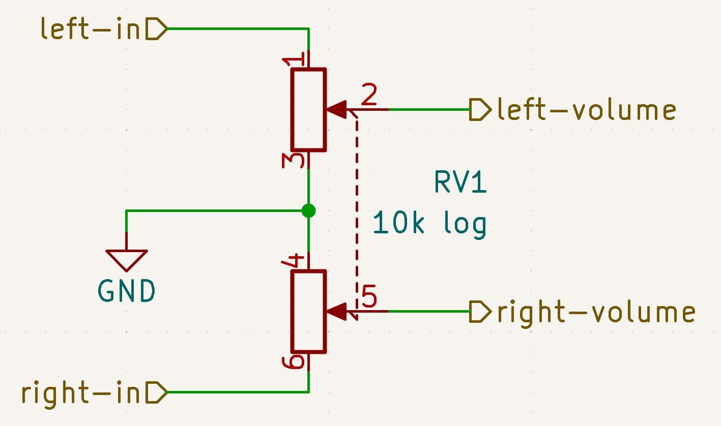
The next part of the circuit is the volume control. This uses a simple logarithmic potentiometer to divert a varying amount of the signal to ground. This decreases or increases the amplitude of the audio signal without adding distortion or clipping. The logarithmic potentiometer should allow the volume to feel more “linear”, since humans hear on a logarithmic scale.
Equalizer
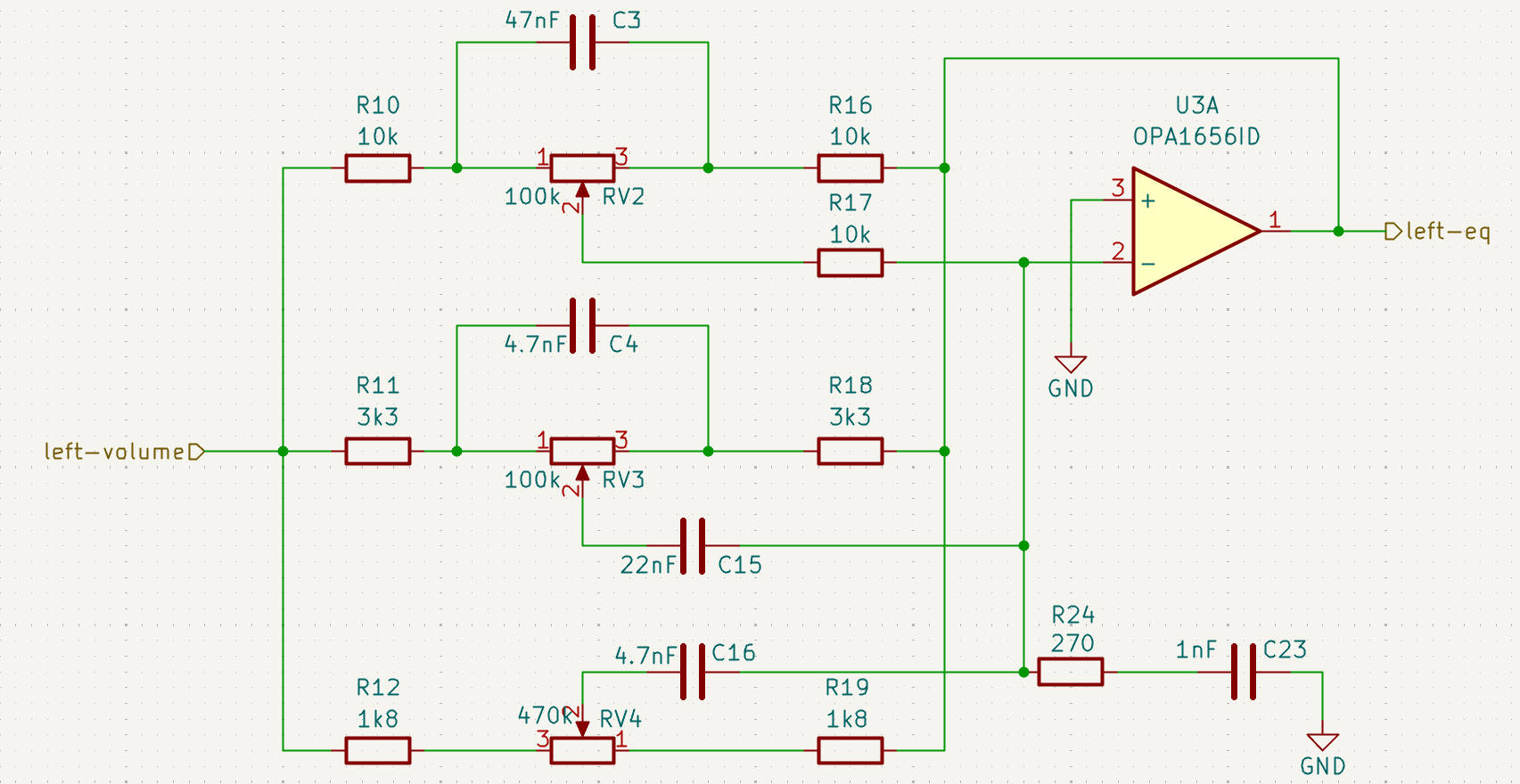
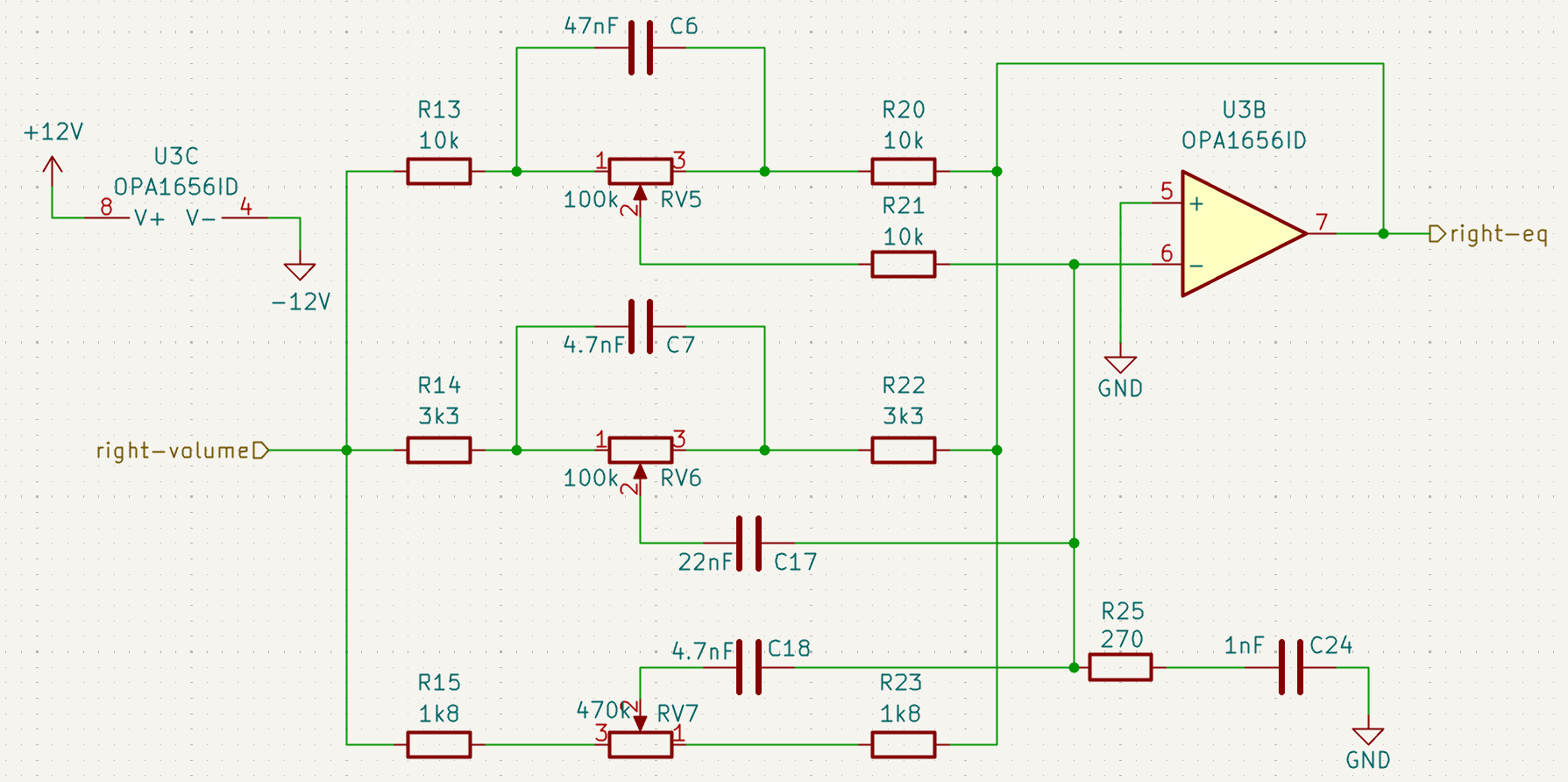
For the equalizer I decided to use a fairly common 3-band active Baxandall equalizer. This design allows independent control over low, mid, and high frequencies, letting the user boost or cut different parts of the audio spectrum. Because the circuit is active (it uses an op amp), it can both attenuate and amplify certain frequency ranges. Passive tone controls can only reduce frequencies, not boost them.
The Baxandall equalizer works by using RC networks inside the op amp’s feedback path to shape the frequency response of the amplifier. Rather than splitting the signal into completely separate frequency bands, these networks modify how the amplifier responds to different frequencies. By adjusting the potentiometers, the amount of feedback at certain frequencies changes, which increases or decreases the gain for those frequency ranges.
Each tone control targets a different part of the audio spectrum:
-
Low frequencies are controlled using a network that behaves like a low-pass response, affecting bass content.
-
High frequencies are controlled using a network that behaves like a high-pass response, affecting treble content.
-
Mid frequencies are controlled with a network that produces a band-shaped response centred around the middle of the audio spectrum.
Adjusting the potentiometers changes how strongly each of these networks influences the feedback of the op amp, allowing the gain at those frequencies to be increased or decreased. The op amp stage ultimately produces a single output signal whose gain varies with frequency, which is what creates the equalization effect.
Feel free to check out this to get a better understanding of equalisers. There is some really good information on Baxandall eqs in it too.
All op amps in schematics are OPA1656ID. They very low distortion and very low noise and are relatively cheap.
Next Steps
Now that I have completed a lot of the preliminary systems, my plan is to make a pcb layout and print the pcb using my schools free pcb printer. I want to go to the lab and test everything out on an oscilloscope before I finalize any designs. I will also continue to design the rest of the schematics, namely the active crossover, and the class d amplifier. The class d amplifier will likely be entirely from the datasheets so I think most of the hard design parts of this project are completed.
Stay tuned for updates.